文章目录
- 一、原理图
- 二、工程代码
avalon 读数据

avalon 写数据


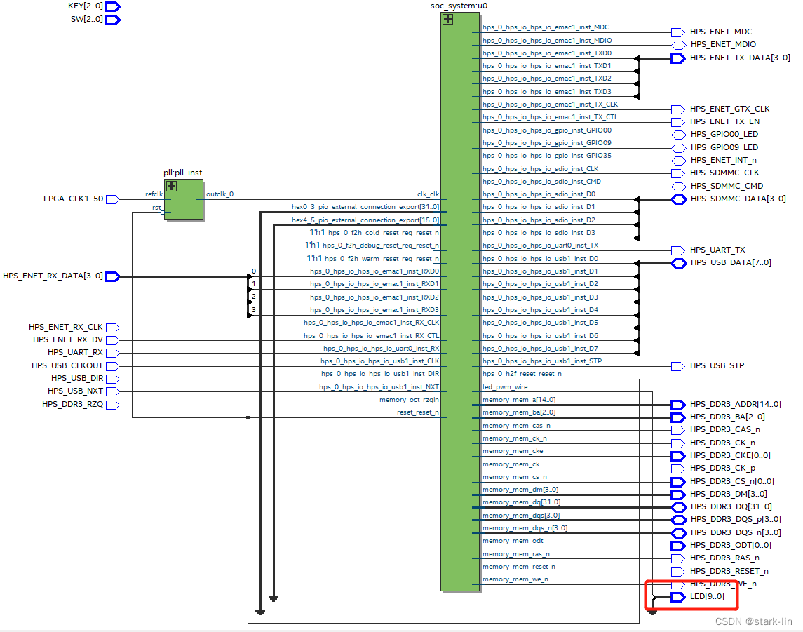
一、原理图
 文章来源:https://uudwc.com/A/y5qop
二、工程代码
1.hps_0.h文章来源地址https://uudwc.com/A/y5qop
#ifndef _ALTERA_HPS_0_H_
#define _ALTERA_HPS_0_H_

/*
 * This file was automatically generated by the swinfo2header utility.
 *
 * Created from SOPC Builder system 'soc_system' in
 * file './soc_system.sopcinfo'.
 */

/*
 * This file contains macros for module 'hps_0' and devices
 * connected to the following masters:
 *   h2f_axi_master
 *   h2f_lw_axi_master
 *
 * Do not include this header file and another header file created for a
 * different module or master group at the same time.
 * Doing so may result in duplicate macro names.
 * Instead, use the system header file which has macros with unique names.
 */

/*
 * Macros for device 'sld_hub_controller_system_0_link', class 'altera_mm_debug_link'
 * The macros are prefixed with 'SLD_HUB_CONTROLLER_SYSTEM_0_LINK_'.
 * The prefix is the slave descriptor.
 */
#define SLD_HUB_CONTROLLER_SYSTEM_0_LINK_COMPONENT_TYPE altera_mm_debug_link
#define SLD_HUB_CONTROLLER_SYSTEM_0_LINK_COMPONENT_NAME sld_hub_controller_system_0_link
#define SLD_HUB_CONTROLLER_SYSTEM_0_LINK_BASE 0x0
#define SLD_HUB_CONTROLLER_SYSTEM_0_LINK_SPAN 128
#define SLD_HUB_CONTROLLER_SYSTEM_0_LINK_END 0x7f

/*
 * Macros for device 'pwm_0', class 'pwm'
 * The macros are prefixed with 'PWM_0_'.
 * The prefix is the slave descriptor.
 */
#define PWM_0_COMPONENT_TYPE pwm
#define PWM_0_COMPONENT_NAME pwm_0
#define PWM_0_BASE 0x80
#define PWM_0_SPAN 16
#define PWM_0_END 0x8f

/*
 * Macros for device 'sysid_qsys', class 'altera_avalon_sysid_qsys'
 * The macros are prefixed with 'SYSID_QSYS_'.
 * The prefix is the slave descriptor.
 */
#define SYSID_QSYS_COMPONENT_TYPE altera_avalon_sysid_qsys
#define SYSID_QSYS_COMPONENT_NAME sysid_qsys
#define SYSID_QSYS_BASE 0x1000
#define SYSID_QSYS_SPAN 8
#define SYSID_QSYS_END 0x1007
#define SYSID_QSYS_ID 2899645186
#define SYSID_QSYS_TIMESTAMP 1658294069

/*
 * Macros for device 'dipsw_pio', class 'altera_avalon_pio'
 * The macros are prefixed with 'DIPSW_PIO_'.
 * The prefix is the slave descriptor.
 */
#define DIPSW_PIO_COMPONENT_TYPE altera_avalon_pio
#define DIPSW_PIO_COMPONENT_NAME dipsw_pio
#define DIPSW_PIO_BASE 0x4000
#define DIPSW_PIO_SPAN 16
#define DIPSW_PIO_END 0x400f
#define DIPSW_PIO_BIT_CLEARING_EDGE_REGISTER 1
#define DIPSW_PIO_BIT_MODIFYING_OUTPUT_REGISTER 0
#define DIPSW_PIO_CAPTURE 0
#define DIPSW_PIO_DATA_WIDTH 3
#define DIPSW_PIO_DO_TEST_BENCH_WIRING 0
#define DIPSW_PIO_DRIVEN_SIM_VALUE 0
#define DIPSW_PIO_EDGE_TYPE NONE
#define DIPSW_PIO_FREQ 50000000
#define DIPSW_PIO_HAS_IN 0
#define DIPSW_PIO_HAS_OUT 1
#define DIPSW_PIO_HAS_TRI 0
#define DIPSW_PIO_IRQ_TYPE NONE
#define DIPSW_PIO_RESET_VALUE 0

/*
 * Macros for device 'button_pio', class 'altera_avalon_pio'
 * The macros are prefixed with 'BUTTON_PIO_'.
 * The prefix is the slave descriptor.
 */
#define BUTTON_PIO_COMPONENT_TYPE altera_avalon_pio
#define BUTTON_PIO_COMPONENT_NAME button_pio
#define BUTTON_PIO_BASE 0x5000
#define BUTTON_PIO_SPAN 16
#define BUTTON_PIO_END 0x500f
#define BUTTON_PIO_BIT_CLEARING_EDGE_REGISTER 1
#define BUTTON_PIO_BIT_MODIFYING_OUTPUT_REGISTER 0
#define BUTTON_PIO_CAPTURE 0
#define BUTTON_PIO_DATA_WIDTH 3
#define BUTTON_PIO_DO_TEST_BENCH_WIRING 0
#define BUTTON_PIO_DRIVEN_SIM_VALUE 0
#define BUTTON_PIO_EDGE_TYPE NONE
#define BUTTON_PIO_FREQ 50000000
#define BUTTON_PIO_HAS_IN 0
#define BUTTON_PIO_HAS_OUT 1
#define BUTTON_PIO_HAS_TRI 0
#define BUTTON_PIO_IRQ_TYPE NONE
#define BUTTON_PIO_RESET_VALUE 0

/*
 * Macros for device 'hex0_3_pio', class 'altera_avalon_pio'
 * The macros are prefixed with 'HEX0_3_PIO_'.
 * The prefix is the slave descriptor.
 */
#define HEX0_3_PIO_COMPONENT_TYPE altera_avalon_pio
#define HEX0_3_PIO_COMPONENT_NAME hex0_3_pio
#define HEX0_3_PIO_BASE 0x6000
#define HEX0_3_PIO_SPAN 16
#define HEX0_3_PIO_END 0x600f
#define HEX0_3_PIO_BIT_CLEARING_EDGE_REGISTER 0
#define HEX0_3_PIO_BIT_MODIFYING_OUTPUT_REGISTER 0
#define HEX0_3_PIO_CAPTURE 1
#define HEX0_3_PIO_DATA_WIDTH 32
#define HEX0_3_PIO_DO_TEST_BENCH_WIRING 0
#define HEX0_3_PIO_DRIVEN_SIM_VALUE 0
#define HEX0_3_PIO_EDGE_TYPE RISING
#define HEX0_3_PIO_FREQ 50000000
#define HEX0_3_PIO_HAS_IN 1
#define HEX0_3_PIO_HAS_OUT 0
#define HEX0_3_PIO_HAS_TRI 0
#define HEX0_3_PIO_IRQ_TYPE NONE
#define HEX0_3_PIO_RESET_VALUE 0

/*
 * Macros for device 'hex4_5_pio', class 'altera_avalon_pio'
 * The macros are prefixed with 'HEX4_5_PIO_'.
 * The prefix is the slave descriptor.
 */
#define HEX4_5_PIO_COMPONENT_TYPE altera_avalon_pio
#define HEX4_5_PIO_COMPONENT_NAME hex4_5_pio
#define HEX4_5_PIO_BASE 0x7000
#define HEX4_5_PIO_SPAN 16
#define HEX4_5_PIO_END 0x700f
#define HEX4_5_PIO_BIT_CLEARING_EDGE_REGISTER 0
#define HEX4_5_PIO_BIT_MODIFYING_OUTPUT_REGISTER 0
#define HEX4_5_PIO_CAPTURE 1
#define HEX4_5_PIO_DATA_WIDTH 16
#define HEX4_5_PIO_DO_TEST_BENCH_WIRING 0
#define HEX4_5_PIO_DRIVEN_SIM_VALUE 0
#define HEX4_5_PIO_EDGE_TYPE RISING
#define HEX4_5_PIO_FREQ 50000000
#define HEX4_5_PIO_HAS_IN 1
#define HEX4_5_PIO_HAS_OUT 0
#define HEX4_5_PIO_HAS_TRI 0
#define HEX4_5_PIO_IRQ_TYPE NONE
#define HEX4_5_PIO_RESET_VALUE 0


#endif /* _ALTERA_HPS_0_H_ */
- pwm_logic.v
module pwm_logic(
	clk,
	rst_n,
	cnt_en,
	counter_arr,
	counter_ccr,
	o_pwm
);
	input clk;	//时钟输入
	input rst_n;	//复位输入,低电平复位
	input cnt_en;	//计数使能信号
	input [31:0]counter_arr;//输入32位预重装值
	input [31:0]counter_ccr;//输入32位输出比较值
	output reg o_pwm;	//pwm输出信号

	reg [31:0]counter_ccr_r;

	always@(posedge clk)
	if(!counter)
		counter_ccr_r <= counter_ccr;
	else
		counter_ccr_r <= counter_ccr_r;

	reg [31:0]counter;//定义32位计数器
	always@(posedge clk or negedge rst_n)
	if(!rst_n)
		counter <= 32'd0;
	else if(cnt_en)begin
		if(counter == 0)
			counter <= counter_arr;//计数到0,加载自动预重装寄存器值
		else
			counter <= counter - 1'b1;//计数器自减1
	end
	else
		counter <= counter_arr;	//没有使能时,计数器值等于预重装寄存器值

	always@(posedge clk or negedge rst_n)
	if(!rst_n)	//让PWM输出信号复位时输出低电平
		o_pwm <= 1'b0;
	else if(counter >= counter_ccr_r)//计数值大于比较值
		o_pwm <= 1'b0;	//输出为0
	else	//计数值小于比较值
		o_pwm <= 1'b1; //输出为1

endmodule
- pwm_avalon_port.v
module pwm_avalon_port(
	clk,
	reset_n,

	as_chipselect,
	as_address,
	as_write,
	as_readdata,
	as_writedata,

	o_pwm
);

	input clk;
	input reset_n;

	input as_chipselect;
	input [1:0]as_address;
	input as_write;
	output reg [31:0]as_readdata;
	input [31:0]as_writedata;

	output o_pwm;


	reg control;
	reg [31:0]counter_arr;
	reg [31:0]counter_ccr;


	pwm_logic pwm_generator(
		.clk(clk),
		.rst_n(reset_n),
		.cnt_en(control),
		.counter_arr(counter_arr),
		.counter_ccr(counter_ccr),
		.o_pwm(o_pwm)
	);

	//写预设寄存器
	always@(posedge clk or negedge reset_n)
	if(!reset_n)
		counter_arr <= 32'd0;
	else if(as_chipselect && as_write && (as_address == 0))
		counter_arr <= as_writedata;
	else
		counter_arr <= counter_arr;

	//写比较通道寄存器
	always@(posedge clk or negedge reset_n)
	if(!reset_n)
		counter_ccr <= 32'd0;
	else if(as_chipselect && as_write && (as_address == 1))
		counter_ccr <= as_writedata;
	else
		counter_ccr <= counter_ccr;

	//写控制寄存器
	always@(posedge clk or negedge reset_n)
	if(!reset_n)
		control <= 1'd0;
	else if(as_chipselect && as_write && (as_address == 2))
		control <= as_writedata[0];
	else
		control <= control;

//读寄存器逻辑
	always@(posedge clk or negedge reset_n)
	if(!reset_n)
		as_readdata <= 32'd0;
	else if(as_chipselect)begin
		case(as_address)
			0:as_readdata <= counter_arr;
			1:as_readdata <= counter_ccr;
			2:as_readdata <= control;
			default:as_readdata <= 32'd0;
		endcase
	end

endmodule
- main.c
/*
 * pwm_test.c
 *
 *  Created on: 2022年6月16日
 *      Author: 86130
 */


#include <stdio.h>
#include <unistd.h>
#include <sys/mman.h>
#include <fcntl.h>

#define soc_cv_av

#include "hwlib.h"
#include "socal/socal.h"
#include "socal/hps.h"
#include "hps_0.h"
#define HW_RGES_BASE (ALT_STM_OFST)
#define HW_RGES_SPAN (0x04000000)
#define HW_RGES_MASK (HW_RGES_SPAN - 1)

typedef struct{
	volatile unsigned long arr;
	volatile unsigned long ccr;
	volatile unsigned long en;
}PWM;
PWM *my_pwm;

int init_fpga(void *virtual_base){
	int fd;
	void *per_virtual_base;
	fd = open("/dev/mem", (O_RDWR|O_SYNC));
	if(fd == -1){
		printf("ERROR: open is failed!\n");
		exit(0);
	}
	per_virtual_base = mmap(NULL, HW_RGES_SPAN, (PROT_READ|PROT_WRITE), MAP_SHARED, fd, HW_RGES_BASE);
	if(per_virtual_base == MAP_FAILED){
		printf("ERROR: mmap is failed!\n");
		close(fd);
	}
	my_pwm = (PWM *)(per_virtual_base + ((unsigned long)(ALT_LWFPGASLVS_OFST + PWM_0_BASE) & (unsigned long)(HW_RGES_MASK)));
	my_pwm->arr = 1000000;
	my_pwm->ccr = 0;
	my_pwm->en = 1;
	virtual_base = per_virtual_base;
	return fd;
}

int main(){
	int fd;
	void *virtual_base;
	int temp = -1000000;
	fd = init_fpga(virtual_base);
	while(1){
		temp = temp + 100;
		if(temp > 1000000){
			temp = -1000000;
		}
		else if(temp < 0){
			my_pwm->ccr = -temp;
		}
		else{
			my_pwm->ccr = temp;
		}
		usleep(100);//100us
	}
	if(munmap(virtual_base, HW_RGES_SPAN) == -1){
		printf("ERROR: munmap is failed!\n");
		close(fd);
	}
	close(fd);
	return 0;
}
